Establishing Sensor Level Telemetry Architecture for Shared Machining Cells
Sensor level telemetry in shared machining cells requires sub-millisecond PTP time alignment and edge context binding to isolate client multi-tenant data streams.

Bus
Capturing sensor data in shared machining cells begins right at the machine tool, where physical forces become electrical signals. CNC milling and turning centers are brutal environments for logging hardware: high-voltage variable frequency drives, switching power supplies, flood coolant, and relentless shock loads degrade raw analog signals before they ever reach an analog-to-digital converter. Wiring piezoelectric vibration sensors, Hall-effect current transformers, acoustic emission sensors, and thermocouples requires strict physical separation.
Running signal cables parallel to spindle motor leads causes capacitive noise spikes above two volts, which completely swamps vibration signals during heavy cuts.
Transceiver selection comes down to bandwidth. IO-Link interfaces work well for digital process sensors sampled under one hundred Hertz, such as coolant pressure switches, chip conveyor jam sensors, and inductive tool positioners. High-frequency structural vibration and spindle bearing acoustic emissions, however, require direct differential analog runs straight to local digitizers.
Piezoelectric accelerometers tracking high-frequency chatter need Integrated Electronics Piezo-Electric interfaces that supply a constant current while reading dynamic voltage swings up to twenty kilohertz. Digitizing these signals right at the sensor minimizes line capacitance and isolates the signal path from electromagnetic interference.
| Sensor Type | Bandwidth / Sampling Rate | Physical Interface | Noise Immunity Level | Maximum Cable Length |
|---|---|---|---|---|
| Piezoelectric Accelerometer | 10 Hz to 20 kHz | IEPE Differential Analog | High (Shielded Twisted Pair) | 15 meters |
| Hall-Effect Current Transducer | DC to 2 kHz | 4-20 mA Current Loop | Very High (Current Mode) | 50 meters |
| Acoustic Emission Sensor | 50 kHz to 500 kHz | High-Speed BNC Coaxial | Moderate (Double Shielded) | 5 meters |
| Thermocouple (Type K) | 1 Hz to 10 Hz | IO-Link Digital Master | High (Digitized at Head) | 20 meters |
Retrofitting telemetry onto an existing CNC machine requires a strict sequence. Mechanical mounting mistakes directly distort the readings.
- Clean the structural mounting face on the spindle housing using solvent to remove any oil or cutting fluid film.
- Stud-mount the piezoelectric accelerometer onto the solid machine casting using a torque wrench calibrated to two Newton-meters. Magnetic mounts reduce resonant frequency response.
- Route shielded twisted-pair transducer cables through flexible liquid-tight steel conduit separated from machine high-voltage power lines by at least three hundred millimeters.
- Terminate signal cable shielding at a single grounding point inside the edge telemetry enclosure to avoid ground loops.
- Connect current transformers to individual spindle and axis motor power phases inside the main cabinet, verifying transformer polarity against motor lead labels.
- Energize the local analog-to-digital converter enclosure and verify baseline noise levels with machine power on but spindle stopped.
Running analog transducer shields through common power conduits introduces inverter noise into bearing vibration data, triggering false alarms and premature component replacements.


Clock
Time alignment across distributed sensors determines whether telemetry can tie physical readings back to specific tool cuts. Multi-axis machines often cut at feed rates above twenty meters per minute. At those speeds, a ten-millisecond mismatch between a spindle current spike and an acceleration peak translates to three hundred micrometers of spatial uncertainty.
Standard Network Time Protocol over enterprise Ethernet drifts anywhere from one to fifty milliseconds ~ far too much jitter to map vibration anomalies back to specific G-code blocks.

Precision Time Synchronization Protocols
IEEE 1588 Precision Time Protocol fixes drift by stamping packets in hardware at the physical network layer. Switches with transparent clock hardware track and correct transmission delays across every hop in the local switch fabric. A central Grandmaster clock keeps edge nodes, CNC controllers, and data loggers aligned to within sub-microsecond bounds.
Keeping that sync under heavy traffic requires dedicated switches that prioritize PTP sync messages using IEEE 802.1Qbv time-aware shaping.
Sub-millisecond synchronization across acoustic emission and spindle current sensors keeps phase drift under two degrees at spindle speeds of twenty-four thousand RPM.
Phase Alignment across Heterogeneous Data Streams
Merging slow controller state data with fast sensor streams requires time-base interpolation. CNC controllers output axis positions, active tool numbers, and feed rate overrides through internal software APIs every ten to one hundred milliseconds. Sensor edge nodes sample accelerometers at forty thousand samples per second per channel.
The edge gateway attaches PTP hardware timestamps to high-frequency analog blocks as frames arrive, then sub-sampling algorithms align the slow controller updates against the fast sensor data using the IEEE 1588 master clock reference.
Plant managers must weigh the cost of PTP-compliant managed switches against the operational risk of phase drift across multi-spindle cells. Whether low-cost wireless ultra-wideband time sync can replace wired PTP networks without losing sub-microsecond determinism remains an active question across the machining sector.

Isolation
Raw voltage waveforms need operational context to be useful, especially in shared cells running jobs for multiple clients on the same equipment. Unlabeled vibration data has almost no diagnostic or commercial value on its own. The telemetry system tags real-time sensor streams with job IDs, tenant customer keys, tool codes, material specs, and tolerance limits at the cell edge before sending data downstream.

Dynamic Context Injection and Workpiece Tagging
Edge gateways pull execution state straight from CNC controllers through interfaces like MTConnect, Fanuc FOCAS, or Siemens OPC UA servers. As the controller runs through program blocks, the edge node reads the active G-code block number, feed rate, spindle override, and tool index, prepending this metadata to the timestamped sensor streams. When a shared cell switches from roughing an aluminum aerospace bracket for one customer to finishing a titanium medical implant for another, the telemetry context tag updates immediately without breaking stream continuity.
The ISO 23247 framework for digital twin manufacturing dictates explicit metadata binding at the edge, invalidating unmapped sensor streams during multi-client production runs.

Data Segregation in Shared Manufacturing Cells
Shared machining environments need strict data separation to protect customer intellectual property. Cutting signatures and vibration spectra can reveal proprietary tooling geometry, feeds, speeds, and toolpath strategies. Modern edge architectures use containerized pipelines and cryptographic tenant isolation, encrypting sensor streams at the cell gateway with tenant public keys so each customer’s cloud storage can only decrypt its assigned job execution telemetry.
Losing context during operation undermines the value of telemetry. Several common scenarios cause data gaps or misattribution during automated runs:
- Unmapped Tool Changes occur when automatic tool changers swap cutters without updating the active tool identification string in the edge gateway buffer.
- Buffer Overwrites happen when edge memory buffers drop metadata packets during an unexpected controller reboot while continuous analog sampling continues.
- Stale Program State appears when operators restart a program from a mid-block location without running header setup scripts.
- Cross-Tenant Leakage occurs when unencrypted local MQTT brokers broadcast combined cell telemetry to unauthorized internal cell monitoring dashboards.
Contract manufacturing agreements often specify IP isolation standards down to the packet header level, placing liability on cell operators who mix customer telemetry streams on unencrypted message brokers.
Payload
Streaming uncompressed raw sensor data across multi-machine cells quickly saturates local networks. A single machine equipped with four accelerometers sampled at forty kilohertz generates over six hundred megabytes of raw binary telemetry every minute ~ meaning a ten-machine cell produces over three hundred gigabytes per shift. Edge nodes process, compress, and filter raw waveforms locally to keep uplink bandwidth requirements manageable.

How Do High-Frequency Edge Nodes Prevent Buffer Overflows during Unaligned Tooling Updates?
Edge gateways use dedicated circular ring buffers in real-time memory to absorb timing spikes caused by sudden controller state updates. When an unaligned tool change or manual override occurs, state data arrives out of sequence relative to continuous sensor feeds. The gateway holds incoming analog frames in the ring buffer while re-aligning metadata tags.
If buffer usage reaches eighty percent capacity, local compute kernels dynamically convert raw time-domain waveforms into frequency-domain spectral summaries, preserving transmission flow without dropping tool-contact data.
Serialization Schemas for High-Frequency Telemetry
Choosing data serialization formats determines CPU utilization on edge hardware and bandwidth consumption on cell networks. Text-based formats like JSON or XML introduce massive parsing overhead and text formatting redundancy. Binary serialization protocol formats like Protocol Buffers, FlatBuffers, or Apache Avro reduce serialization latency and package size significantly.
Message brokers running MQTT Sparkplug B or OPC UA PubSub over TSN leverage binary payloads to maintain steady data transit speeds across cellular or bandwidth-constrained shop-floor networks.
| Serialization Format | Payload Size Overhead | Edge CPU Parsing Time | Bandwidth Consumption | Schema Evolution Support |
|---|---|---|---|---|
| JSON / REST API | High (350%) | 12.4 microseconds | 4.2 Mbps per channel | Poor (Manual Parsing) |
| MQTT Sparkplug B (Protobuf) | Low (15%) | 1.1 microseconds | 0.8 Mbps per channel | High (Backward Compatible) |
| OPC UA PubSub (Binary) | Moderate (35%) | 2.3 microseconds | 1.1 Mbps per channel | High (Strict Information Models) |
| Raw Binary UDP Stream | Very Low (2%) | 0.2 microseconds | 0.6 Mbps per channel | None (Hardcoded Offsets) |
Choosing an edge serialization schema comes down to balancing edge hardware limits, network bandwidth caps, and downstream analytics needs:
- Hardware Processing Margins determine whether low-power edge gateways can handle real-time Protocol Buffer serialization without dropping incoming sensor frames.
- Network Bandwidth Caps set maximum continuous transmission rates allowed before edge nodes shift from raw waveform streaming to spectral summary mode.
- Downstream Parser Compatibility dictates whether cloud analytics engines require standardized OPC UA information models or flexible custom binary parsers.
- Schema Versioning Resilience ensures future additions of new sensor channels do not break historical data pipeline decoding applications.
Edge compute nodes execute local signal FFT windowing when uplink bandwidth saturates, preserving frequency peak telemetry while shedding raw time-domain waveforms.
Integrated edge gateways are rated for extreme network data bursts in specifications, but unannounced packet loss occurs once internal dynamic buffers fill completely.


Benchmark
Establishing clean signal baselines ensures telemetry architectures correctly separate cutting dynamics from external background noise. Machining cells contain plenty of structural vibration sources unrelated to cutting: auxiliary coolant pumps, chip conveyors, cabinet cooling fans, and adjacent hydraulic presses all transfer mechanical energy through machine frames. Sensor networks installed without baseline noise spectral mapping register false diagnostic alerts triggered entirely by non-cutting peripheral equipment.
Noise Floor Determination in Multi-Tool Cutting Regimes
Establishing the noise floor requires logging baseline spectra across four operational machine states: powered down with control electrics active, hydraulic and coolant systems running, spindle rotating free across full speed range, and active air-cutting tool path movement. Subtracting ambient mechanical noise spectra from total cutting vibration isolates true tool-workpiece interaction dynamics. Signal-to-noise ratio verification ensures sensor channels retain sufficient dynamic range to capture subtle tool wear indications before catastrophic tool breakage occurs.
Vibration telemetry recorded without filtering coolant pump harmonics masks early flank wear on the cutter.

Worked Baseline Calculation for Signal-to-Noise Ratio
Consider a single-point piezoelectric accelerometer installed on a 5-axis machining head monitoring an end mill cutting Ti-6Al-4V titanium alloy. The accelerometer voltage sensitivity equals one hundred millivolts per g of acceleration, connected to a 24-bit analog-to-digital converter set to a dynamic input voltage range of plus or minus five volts.
Ambient testing with coolant pumps running and spindle rotating at ten thousand RPM free-spin reveals a background RMS noise floor voltage of 0.8 millivolts across the zero-to-ten kilohertz spectrum. The physical noise floor acceleration calculates directly:
Noise Floor = 0.8 mV / (100 mV/g) = 0.008 g RMS
During stable cutting on the titanium part, active engagement generates a vibration signal voltage of forty-five millivolts RMS. The cutting signal acceleration calculates as:
Signal Amplitude = 45 mV / (100 mV/g) = 0.45 g RMS
The operational signal-to-noise ratio for this physical telemetry channel is calculated using standard logarithmic amplitude ratios:
SNR = 20 log10(0.45 g / 0.008 g) = 20 log10(56.25) = 35.0 dB
If tool flank wear increases cutter land rubbing, vibration rises to one hundred twenty millivolts RMS (1.2 g RMS), pushing the operational SNR to 43.5 dB. However, if a secondary machine tool mounted on the same floor slab energizes a high-pressure coolant booster pump, the background noise floor voltage increases to 8.0 millivolts RMS (0.08 g RMS). Under these degraded background conditions, the initial nominal cutting SNR drops dramatically:
Degraded SNR = 20 log10(0.45 g / 0.08 g) = 20 log10(5.625) = 15.0 dB
A signal-to-noise ratio of fifteen decibels leaves insufficient headroom to detect early stage tool chipping, as harmonic noise peaks obscure structural cutter excitation. Re-anchoring machine isolation dampers restores baseline noise floor levels.
Establish clean sensor baseline measurements prior to altering tool holder hardware specifications, or physical telemetry data becomes impossible to compare across historical machining runs.

Gate
Rolling out sensor telemetry across shared machining cells requires structured stage-gate approvals tied to operational readiness metrics. Investing capital in plant-wide sensor retrofits before validating single-cell data integrity risks compounding architecture design errors across multiple production lines. Phase gates enforce operational validation checks before advancing telemetry scale-up and signing procurement contracts for edge hardware.
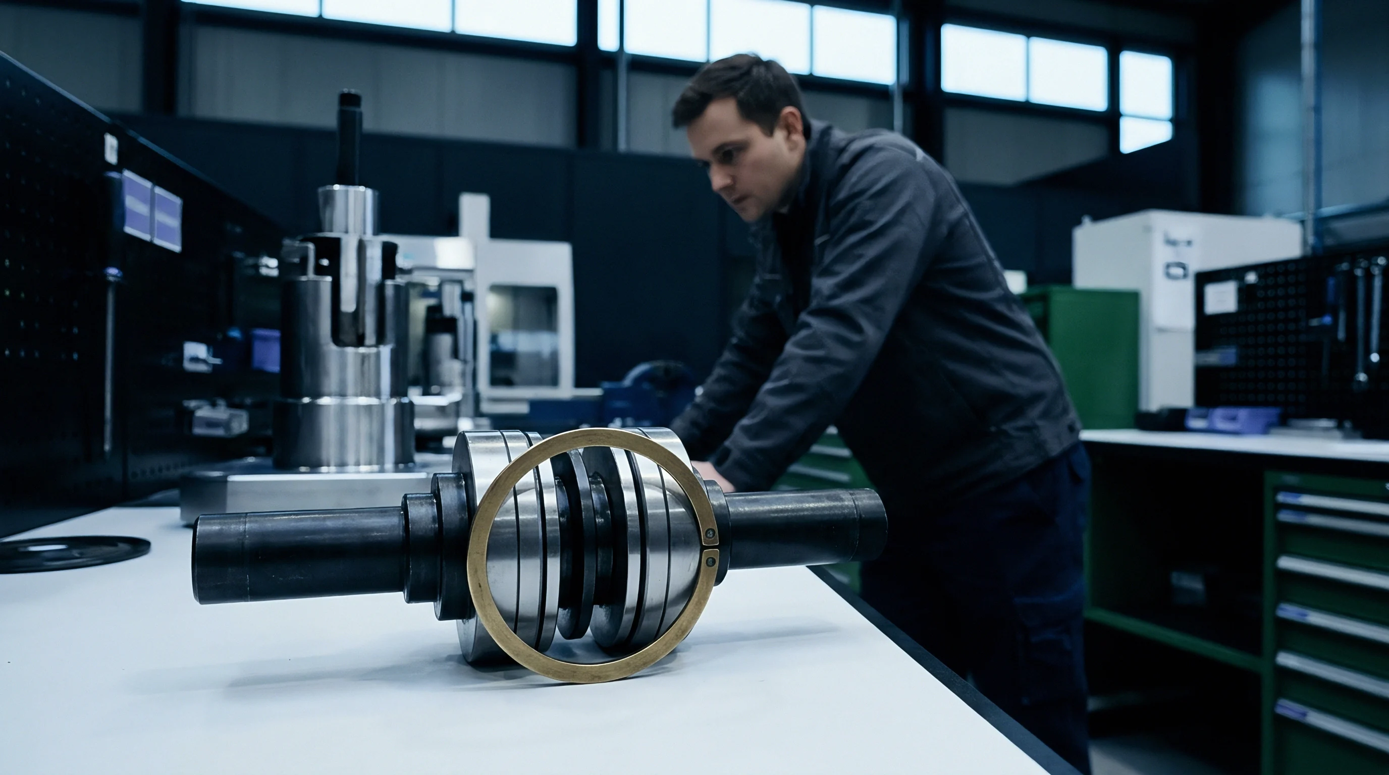
Capital Deployment Stages for Telemetry Retrofits
The deployment sequence begins with Phase Zero, establishing physical feasibility on a single pilot machining cell. Engineering teams validate sensor mounting methods, verify signal-to-noise baselines, and test time synchronization protocols under maximum shop-floor electromagnetic load. Phase One introduces automated context injection, verifying that machine state variables map accurately to dynamic sensor payloads across multi-tenant part programs.
Phase Two scales the architecture across all cell machines, integrating automated telemetry parsing into cloud storage backbones and factory execution systems.
Dossier Requirements for Telemetry System Acceptance
Passing telemetry system qualification gates demands complete documentary evidence on file. Capital deployment reviews require structured validation dossiers before approving expansion capital expenditure.
- Signal Integrity Logs verifying that sensor signal-to-noise ratios stay above thirty decibels across all operating spindle speeds and cutting regimes.
- Clock Drift Calibration Records proving IEEE 1588 PTP synchronization skew stays below fifty microseconds during seventy-two hours of continuous data logging.
- Context Matching Audits demonstrating zero mismatched part serial numbers or tool index codes across one thousand consecutive automated tool changes.
- Data Segregation Cryptographic Validations confirming multi-tenant payload isolation and successful cloud end-point decryption tests.
- Edge Processing Failover Reports documenting edge ring buffer performance and automated payload reduction under network link disconnect scenarios.
Final sign-off on cell telemetry architecture integration occurs when the plant engineering team verifies that baseline noise spectra stay stable across three consecutive shifts of continuous heavy metal cutting. Sign-off moves responsibility from the system integrator to plant operations staff, establishing routine maintenance intervals for sensor calibration checks, cable shield continuity tests, and edge gateway firmware updates.